1904 Ford Arrow
In 1902 Henry Ford was introducing his first production car, the Model A. To publicise the Ford name he built 2 racing cars to compete on the American dirt tracks of the time. The first, named "999", driven by Barney Oldfield, proved a successful racer. The second, named "Arrow", was wrecked in a fatal crash, but was resurrected in 1903 by Henry Ford with the intention of breaking the World land speed record and publicising the introduction of the Model B Ford, scheduled for 1904.

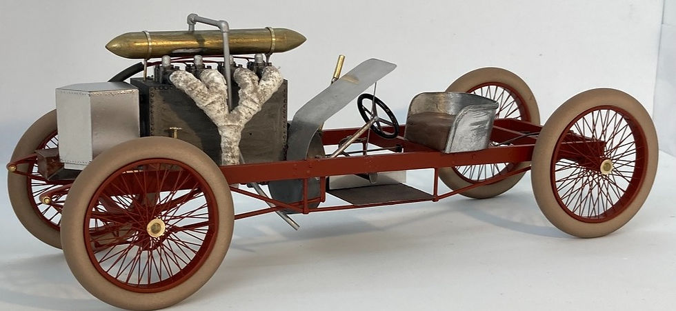
Ford's intent was that the record attempt would be made on the frozen surface of Lake St.Clair near Detroit in January 1904. Assuming the ice surface to be smooth and the air temperature to be freezing, the car was constructed without rear springs, gearbox, or differential and without a cooling radiator. A streamlined header tank for coolant was mounted ahead of the engine, and in the absence of bodywork a metal screen was mounted ahead of the driver. This somewhat crude creation of 4 cylinders and 17 litres was ready to accelerate to the measured mile on January 12th 1904. Cinders were spread on the track to assist traction but the ice proved to be very bumpy rather than smooth as expected. Consequently the car was off the ice surface as much as on it and was virtually out of control for most of the run. Nevertheless, the brave Henry Ford succeeded in completing the measured mile in 39.4 seconds, an average speed of 91.37 mph. Two weeks later William Vanderbilt broke Henry's record by 0.4 seconds in the warmth of a Florida beach.


building the model
PREPARATION
Full working drawings are made to model scale (1/16th) using photos from internet and books. Apart from the wheelbase and track, all other dimensions are educated guesses. The sister car (999) still exists in the Dearborn Museum and is well documented, so much information came from that source, but with the awareness that the two cars were definitely not identical.
CHASSIS
The chassis on the original car was wood beams reinforced with steel plates. The model chassis is fabricated from brass rod, flat strips, and rectangular tubing and soft soldered. The larger rivets are pin heads, the smaller ones are 1/32" polystyrene rod sanded to simulate a round head. The gear wheels of the final drive are polystyrene and the teeth are filed by hand.


ENGINE
The engine is entirely fabricated from Polystyrene supplied in sheet, rod and strip form by Evergreen.
Carburettors and cam covers are cast in Urethane resin from a silicon mold using pre-existing parts as patterns. The streamlined fuel tank above the engine is made from wooden dowel, painted with True-Metal to simulate brass and polished.
The crankshaft is not covered, so the visible parts of con rods and crank pins needed to be shown.


WHEELS and TYRES
Wheel rims are made from two .020" styrene strips temporarily tacked to a disc, having pre-drilled holes for the spokes. Square section .020" strips create the rim walls. Edges are sanded smooth as shown here.

The hub is made from 3 layers of brass tubing recessed to provide a shoulder to seat the spokes.
A jig is created to secure the rim and hub in correct location with each other

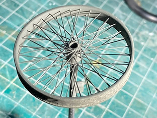
Spokes are cut to length from .011" guitar strings. Each one is passed through one of the rim holes, seated in the recess of the hub, and secured at each end with a drop of crazy glue applied with the point of a needle. The spoke end will remain proud of the rim surface to be removed later.

The second layer of spokes is added, sloped in the reverse direction and located in a second recess on the hub.

The protruding spoke ends are easily removed with a high speed grinder and abrasive disc. Etching primer is sprayed on the finished wheel to ensure finished paint will adhere to the spokes.
When spoking is completed for one side of the wheel, the disc is removed and the tacking marks removed. The wheel is now sufficiently rigid that the jig is not required for spoking the other side of the wheel.

Spoking can now be completed for the other side of the wheel.


Tyres are made from rubber cord cut to precise length. The ends are glued together with crazy glue.
Wheels and tyres are prepared for final painting. Rubber tyres can be successfully painted using acrylic paints and an airbrush.

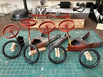
The finished wheels and tyres ready for mounting on the chassis.
The natural rubber look of early tyres is achieved using slightly differing shades of beige oversprayed to give the effect of dirt and wear.